Device Classes
All LoRaWAN end devices provide bi-directional communication, from device to network server through gateway/s and network server to device through a gateway. The messages sent from the end device to the network server are called ‘Uplink messages’ while the messages sent from the network server to the end device are called ‘Downlink messages’.
The LoRaWAN end devices can be categorized into three groups based on the behaviour of how they send and receive messages. These categories are known as mode of operations.
Class A
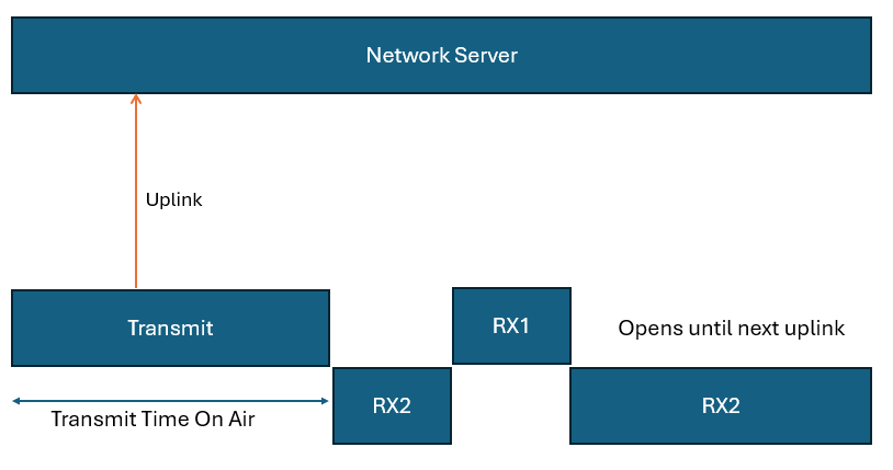
In Class A mode of operation, the end device (or you) can decide when to transmit an uplink message. The time required to complete this transmission is called the Transmit Time On Air.
The device can receive downlink messages from the network server only shortly after it finishes sending an uplink message. In other words, the network server must wait to send a downlink message to the device until it first receives an uplink message from that device.
After sending an uplink message, the device opens two short receive windows:
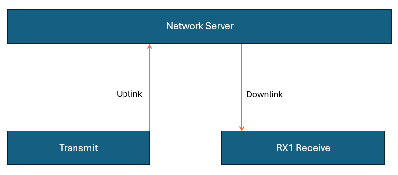
- RX1 (Receive Window 1)
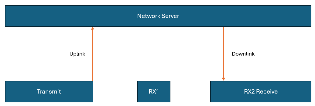
- RX2 (Receive Window 2)
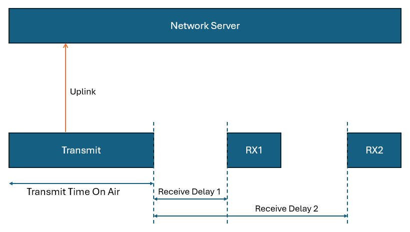
The network server can choose to send a downlink message during either RX1 or RX2, but not both. If the device receives a message during RX1, it does not open RX2.
If no message is received in RX1, the device proceeds to open RX2.
Class A end devices are usually battery-powered and operate with a single or two AAA batteries
Class B
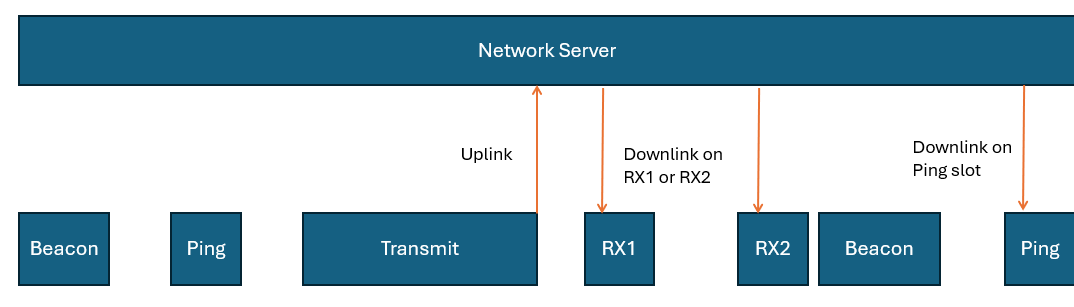
Class B devices build upon the functionality of Class A by adding extra opportunities to receive downlink messages. In addition to the standard receive windows (RX1 and RX2), Class B devices open scheduled receive windows called ping slots at regular intervals.
To make this possible, the network periodically transmits a time-synchronized beacon (both unicast and multicast) via its gateways. These beacons are picked up by the end devices and used to synchronize their internal clocks with the network’s time. This synchronization enables the network server to precisely time downlink messages to a specific device or group of devices during their ping slots. The interval between two beacons is referred to as the beacon period.
Like in Class A, after each uplink transmission, the device still opens the two short receive windows, RX1 and RX2. In addition to that, class B devices receive downlink messages on ping slots.
Class C
Class C end devices offer enhanced communication capabilities compared to Class A by maintaining an almost constant listening state. Except during uplink transmissions, these devices keep their receive windows open, making them ideal for applications that require quick and frequent downlink communication.
This always-on listening mode significantly reduces the delay in receiving downlink messages. For example, it allows real-time actions such as dimming a streetlight or triggering a valve in a water system.
Like Class A, Class C devices use two receive windows, RX1 and RX2. The key difference is that RX2 remains open nearly all the time. After sending an uplink, the device briefly opens RX1 and RX2, after which RX2 stays open continuously until the next uplink occurs. If a downlink is in progress, the device waits before initiating a new uplink to avoid interference.
Latency and Power Trade-offs
Class C devices are known for their minimal downlink latency, outperforming both Class A and Class B in this regard. However, this performance comes at the cost of increased power usage, as the device is in a near-constant receive mode. Because of this, Class C devices are typically powered by a constant power source rather than batteries.
Common Applications
Devices operating in Class C mode are well-suited for scenarios where immediate responsiveness is critical. Some typical use cases include:
- Irrigation (Controlling water pumps, values etc.)
- Street lighting
- Alarm systems
It’s also worth noting that many Class C devices can switch to Class A mode when needed, offering flexibility depending on power and latency requirements.