Spreading Factors
In this lession, you will learn about Spreading Factors (SF) and their impact on LoRa communication.
The Spreading Factor (SF) defines two fundamental values.
The number of raw bits that can be encoded or transmitted by a symbol is SF.
- The number of chirps the symbol can hold is 2SF.
- To understand the behavior of the spreading factor, let’s have a look at a symbol and how the data is encoded by a symbol, and how the symbol is encoded onto the sweep signal to form a modulated chirp.
Symbol
A symbol is a group of bits. One bit contains a single binary value, either a 0 or a 1. The Spreading Factor indicates the number of raw bits that can be transmitted by a symbol. For example, with Spreading Factor 7, you can transmit 7 bits over one symbol. The equation can be written as,
Spreading Factor (SF) = The number of raw bits encoded (transmitted) by a symbol
The following figure shows 7 raw bits encoded by a symbol thus the spreading factor is 7.
| 1 | 1 | 0 | 1 | 1 | 1 | 0 |
|---|
A symbol can have one of the values ranging from 0 to 2SF-1 (in decimal). For example, if the Spreading Factor is 7, a symbol can have one of the values ranging from 0 to 127.
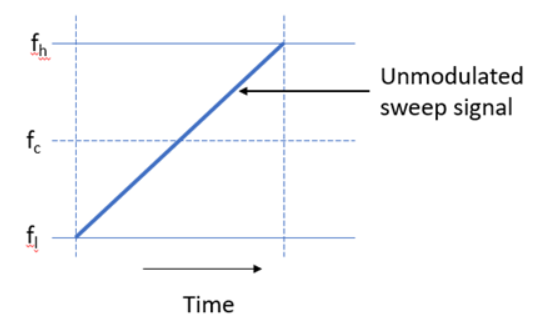
The sweep signal is divided into 2SF steps called chirps. Then the symbol value is encoded onto a sweep signal. The sweep signal is a ramp from the lowest frequency to the highest frequency of a bandwidth called up-chirp or from the highest frequency to the lowest frequency of a bandwidth called down-chirp.
For example, if the spreading factor is 7 the sweep signal is also divided into 27 = 128 chirps. It starts from chirp 0 and ends with chirp 127. The following figure shows an unmodulated sweep signal (up-chirp).
If the symbol holds modulated data, for example, 1000000 binary, the equivalent decimal value is 64. This symbol can be encoded onto the sweep signal and the modulated up-chirp can be illustrated as shown in the image below.

The sweep signal is divided in 2SF = 27 = 128 chirps. The symbol starts from chirp 64 and ends with chirp 127 and cyclically-shifted from chirps 0 to 64. The starting point of the sweep signal indicates the value of the symbol.
Influence of Spreading Factors
Now that you know the spreading factor (SF) represents the number of bits a symbol can transmit. LoRa modulation has a total of 6 spreading factors from SF7 to SF12. Spreading factors influence data rate, time-on-air (TOA), battery life, and receiver sensitivity, as described here.
- Data rate/bit rate - Compared to a higher spreading factor, a lower spreading factor provides a higher bit rate for a fixed bandwidth and the coding rate. For example, SF7 provides a higher bit rate than SF12. If you double the bandwidth, the bit rate also gets doubled for a fixed spreading factor and the coding rate. For example, SF7/250kHz provides 11000 bits/s which is nearly twice the size of 5470 bits/s provided by the SF7/125kHz. The following table presents bit rates calculated with the SF7 and Coding Rate (CR) = 1 for bandwidths, 125, 250, and 500 kHz.
| Spreading Factor | Bandwidth | Bit rate (kbits/s) |
|---|---|---|
| 7 | 125 | 5.5 |
| 7 | 250 | 10.9 |
| 7 | 500 | 21.9 |
Distance - A signal modulated with a larger spreading factor will be able to travel a longer distance. For example, a signal modulated with the SF12 can travel a longer distance than a signal modulated with the SF7.
Time-On-Air - Compared to a lower spreading factor, sending a fixed amount of data (payload) with a higher Spreading Factor and a fixed bandwidth needs longer time-on-air (TOA). In other words, the low spreading factors have short symbol durations while the high spreading factors have long symbol duration. The following figure illustrates how the symbol duration increases as the spreading factor increases.

- Receiver Sensitivity - The larger spreading factors provide a higher receiver sensitivity, for example, SF12 provides a higher receiver sensitivity than the SF7. Usually, LoRa uses higher spreading factors when the signal is weak. The following table shows how spreading factors impact the receiver sensitivity. Note that the higher the spreading factor results in the higher the receiver sensitivity.
| Spreading factor | Receiver sensitivity for bandwidth fixed at 125 kHz |
|---|---|
| SF7 | -123 dBm |
| SF8 | -126 dBm |
| SF9 | -129 dBm |
| SF10 | -132 dBm |
| SF11 | -134.5 dBm |
| SF12 | -137 dBm |
- Battery life - The battery life of an end device is highly dependent on the spreading factor used. Using larger spreading factors results in shorter battery life. The reason is that the signals modulated with the larger spreading factors take longer time-on-air hence the radio transceiver must be active for a long period of time compared to lower spreading factors. The radio transceivers consume more power when they are in the active mode. This results in shorter battery life.
The following figure illustrates how the bit rate and time-on-air (OTA) changes for each spreading factor (SF7-SF12).

Signals modulated with different spreading factors and transmitted on the same frequency channel at the same time do not interfere with each other. The following section briefly describes some important parameters: coding rate, data rate, symbol rate, symbol duration, chirp rate, chirp duration.
Coding Rate
The coding rate represents the proportion of bits that actually carry information. The redundant bits are used for error correction. The error correction can be used to recover the data if they are lost due to interference. Therefore, the error correction mechanism reduces data throughput but increases the sensitivity of the receiver.
LoRa modulation has a total of 4 codes for error correction. The Coding Rate (CR) can be calculated by using the following equation.
CR = 4/(4+CR) where CR = 1,2,3,4.
| Error Correction Code | Coding Rate |
|---|---|
| 1 | 4/5 |
| 2 | 4/6 |
| 3 | 4/7 |
| 4 | 4/8 |
For example, the following symbol carries raw 7 bits with the coding rate = 4/5. The number of bits that carries the actual information can be calculated as,
Spreading Factor X Coding Rate = 7 X 4/5 = 5.6
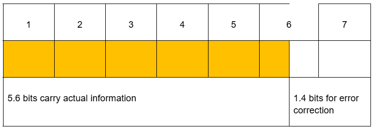
The remaining 1.4 bits are used for the error correction.
If you use a higher coding rate for error correction the number of bits that can be transmitted using a symbol is reduced but the ability to recover the data is increased.
Data Rate
The data rate is the number of bits that are transferred per unit of time. The data rate can be expressed in bits per second (bits/s). The term data rate can be used interchangeably with bit rate. The bit rate can be calculated using the following equation.
Bit Rate = = SF x (BW / 2^SF) x (4(4+CR))
Example: Calculate the bit rate for the following parameters. Bandwidth = 125 kHz, Spreading Factor = 7, Coding Rate =4/5
Solution: The equation can be written by applying the given parameters as shown below.
Bit rate = 7 x (125000 / 128) x (4 / 5) = 5468 bits/s
This is approximately 5470 bits/s, the same bit rate mentioned for SF7 / 125 kHz in the LoRaWAN regional parameters document.
Symbol Rate
The symbol rate is expressed in symbols per second and can be calculated using the following equation.
Bandwidth in Hertz / 2SF
For example, the symbol rate for bandwidth 125kHz and Spreading Factor 7 can be calculated as follows.
Symbol rate = 125000 / 128 = 977 symbols/sec
Symbol Duration
The sweep time of a chirp (up or down) is known as the symbol duration. The symbol duration can be calculated using the following equation.
Symbol Duration = 2SF / Bandwidth in Hertz
figure
TS = Symbol duration, fC = center frequency, fh = upper frequency limit of the bandwidth, fl = lower frequency limit of the bandwidth.
Example: Calculate the symbol rate for the spreading factor 7 and bandwidth 125 kHz.
Solution: Symbol duration = 128 / 125000 = 1.024 ms
chirp Rate
The chirp rate always equals the bandwidth where the bandwidth is expressed in Hertz. The chirp rate is expressed in the number of chirps per second (chirps/sec).
chirp Rate = Bandwidth in Hertz
Example: If the bandwidth is 125kHz, the chirp rate can be written as,
125 kHz = 125000 Hz = 125000 chirps/sec
chirp Duration
The chirp duration can be calculated using the following equation.
chirp Rate = Bandwidth in hertz
Therefore,
chirp Duration = 1/chirp rate = 1/Bandwidth in Hertz
Example: Calculate the chirp duration for the bandwidth 125 kHz.
Solution: chirp duration = 1/125000 = 8µs