Warning
Draft- Under review
Regional Parameters
The LoRaWAN® Regional Parameters document describes the approved frequency channel plans around the world, following regulatory constraints in those regions. The LoRaWAN regional parameters vary slightly from region to region based on different regional spectrum allocations and regulatory requirements. These regional parameters are defined by the technical committee of the LoRa Alliance.
This tutorial is based on the latest LoRaWAN regional parameters document, which is RP002-1.0.4 at the time of this writing. Apart from the regulatory requirements defined by the LoRa Alliance for each channel plan, the local regulatory authorities and the network operators can also impose additional restrictions.
The regional parameters include physical layer parameters such as frequency plans (channel plans), mandatory channel frequencies and data rates for join-request messages, uplink and downlink data rates, Tx output power, dwell time and power control.
The Regional Parameters also include LoRaWAN layer parameters such as maximum payload size. In this tutorial you will learn in detail about the EU863-870 band and US902-928 ISM band. This tutorial also presents some important parameters involved in other channel plans.
Channel Plans
LoRaWAN operates in the Unlicensed ISM (Industrial, Scientific, and Medical) band. The table below lists the latest channel plans and their common names.
| Channel Plan | Common Name |
|---|---|
| EU863-870 | EU868 |
| US902-928 | US915 |
| CN779-787 | CN779 |
| EU433 | EU433 |
| AU915-928 | AU915 |
| CN470-510 | CN470 |
| AS923 | AS923 |
| KR920-923 | KR920 |
| IN865-867 | IN865 |
| RU864-870 | RU864 |
EU863-870 Band
The EU863-870 band can be applied to any region where the radio spectrum use is defined by the ETSI [EN300.220] standard. The EU863-870 band is used in all the European countries, and some countries outside Europe.
EU863-870 default channels
The following three default channels shall be implemented in every end device that supports the EU863-870 band. These channels are used by the end device to broadcast the join-request message. The end device randomly selects one of the default channels to send the join-request message.
| Channel Frequency (MHz) | Bandwidth (kHz) | LoRa data rate | Bit rate | Duty cycle |
|---|---|---|---|---|
| 868.10 | 125 | DR0 – DR5 | 0.3 – 5 kbps | < 1% |
| 868.30 | 125 | DR0 – DR5 | 0.3 – 5 kbps | < 1% |
| 868.50 | 125 | DR0 – DR5 | 0.3 – 5 kbps | < 1% |
The duty cycle limitation of <1% for these three default channels is imposed by the European Telecommunications Standards Institute (ETSI) regulations. By default, the RX1 receive window uses the same channel as the preceding uplink, for example, if the join-request is sent at 868.10 MHz, the RX1 receive window uses 868.10 MHz to listen for the join-accept message.
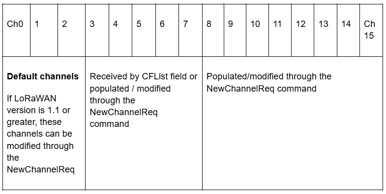
For devices compliant with LoRaWAN version 1.0.x, these three default channels shall not be modified. For devices compliant with LoRaWAN version 1.1 and beyond, these channels may be modified through the NewChannelReq command. All these channels are usable for DR0 – DR5 with 125 kHz bandwidth LoRa modulation and the bit rate ranges from 0.3 – 5 kbps. The EU863-870 band supports a maximum of 16 channels (ch0 – ch15). During end device activation it may receive an optional channel list in the CFlist field of the join-accept message that contains 5 frequencies (ch3 – ch7) in the join-accept message. These are the center frequency of the channels. However, all 16 channels (ch0 – ch15) can be modified (existing channels) or populated (initially blank channels) through the NewChannelReq command under some conditions as mentioned above. The following table shows how the 16 channels are populated/modified. Some end devices only use 8 channels for uplink.
EU863-870 Data Rates
Data rate is the number of bits that are transmitted per unit of time. With the LoRa modulation, the data rate depends on a few factors like spreading factor, bandwidth, and the coding rate. By default, the LoRa modulation uses the Coding Rate = 4/5.
The following table shows the bit rate for each data rate configured with the spreading factor and the bandwidth.
DR0 - DR6 are used for LoRa modulation. DR7 is used for FSK modulation and DR8 - DR11 are used for Long Range Frequency Hopping Spread Spectrum (LR-FHSS).
| Data Rate | Configuration (SF + BW) | Bit rate (bit/s) |
|---|---|---|
| 0 | LoRa: SF12 / 125 kHz | 250 |
| 1 | LoRa: SF11 / 125 kHz | 440 |
| 2 | LoRa: SF10 / 125 kHz | 980 |
| 3 | LoRa: SF9 / 125 kHz | 1760 |
| 4 | LoRa: SF8 / 125 kHz | 3125 |
| 5 | LoRa: SF7 / 125 kHz | 5470 |
| 6 | LoRa: SF7 / 250 kHz | 11000 |
| 7 | ||
| 8 | ||
| 9 | ||
| 10 | ||
| 11 | ||
| 12..14 | ||
| 15 |
As you can see the higher spreading factors use lower bit rates and the lower spreading factors use higher bit rates. However for the same spreading factor, if the bandwidth doubles the data rate also gets doubled. You will learn more about the Spreading Factors in the Spreading Factors chapter.
All EU868-870 end devices must support one of the following data rate options.
- DR0 – DR5 – the minimal data rate set supported to obtain the LoRaWAN certification.
- DR0 – DR7
- DR0 – DR11 – all data rates are implemented in the end device
In Europe, the European Telecommunications Standards Institute (ETSI) creates standards that are used by local regulatory authorities.
EU863-870 Maximum EIRP / ERP
The Effective Isotropic Radiated Power (EIRP) is the total power radiated by an isotropic antenna in a single direction. An isotropic antenna is a hypothetical antenna (an infinitesimally small point in space) which radiates the same intensity of radiation in all directions. The antenna gain is expressed in dBi for isotropic antennas.
The EIRP is calculated using the following equation:
EIRP = Tx Power (dBm) + Antenna gain (dBi) + Cable loss (dBm)
The EIRP is expressed in dBm.
The following table shows the list of EIRP values that can be used to transmit data.
| TX Power | EIRP | Calculated value |
|---|---|---|
| 0 | Max EIRP | +16 dBm |
| 1 | Max EIRP - 2 dB | +16 dBm - 2 dB = +14 dBm |
| 2 | Max EIRP - 4 dB | +16 dBm - 4 dB = +12 dBm |
| 3 | Max EIRP - 6 dB | +16 dBm - 6 dB = +10 dBm |
| 4 | Max EIRP - 8 dB | +16 dBm - 8 dB = +8 dBm |
| 5 | Max EIRP - 10 dB | +16 dBm - 10 dB = +6 dBm |
| 6 | Max EIRP - 12 dB | +16 dBm - 12 dB = +4 dBm |
| 7 | Max EIRP - 14 dB | +16 dBm - 14 dB = +2 dBm |
| 8..14 | RFU | |
| 15 | Defined in [TS001] |
The Max EIRP for EU863-870 is +16dBm. The equivalent Effective Radiated Power (ERP) value is +14dBm (as mentioned in the ETSI [EN300.220]) with the exception of the G3 band that allows ERP = +27dBm.
The above mentioned EIRP and ERP values can also be expressed in milliwatts (mW).
- +16 dBm = 40 mW
- +14 dBm = 25 mW
- +27 dBm = 500 mW
The maximum allowed antenna gain is +2.15 dBi (isotropic antenna) that is equivalent to 0 dBd (half-wave dipole antenna).
EU863-870 Maximum Payload Size
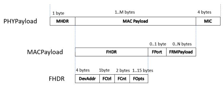
The FRMPayload field of a data message holds application data known as the ‘application payload’. The maximum application payload size (length) varies by data rate (configured with spreading factor and bandwidth). The following figure shows a data message and the FRMPayload field. The size of the FRMPayload field is M-8 bytes where M is the MACPayload size (if theFOpt field is absent).
The following table shows the maximum application payload (FRMPayload) size (N) for different data rates.
| Data Rate | Configuration (SF+BW) | Maximum application payload size (bytes) |
|---|---|---|
| 0 | LoRa: SF12 / 125 kHz | 51 |
| 1 | LoRa: SF11 / 125 kHz | 51 |
| 2 | LoRa: SF10 / 125 kHz | 51 |
| 3 | LoRa: SF9 / 125 kHz | 115 |
| 4 | LoRa: SF8 / 125 kHz | 242 |
| 5 | LoRa: SF7 / 125 kHz | 242 |
| 6 | LoRa: SF7 / 250 kHz | 242 |
| 7 | ||
| 8 | ||
| 9 | ||
| 10 | ||
| 11 | ||
| 12..15 |
EU863-870 Downlink frequencies and data rates
By default, the RX1 receive window uses the same channel for downlink as the preceding uplink channel. Also, the data rate is a fraction of the uplink data rate. The RX2 receive window uses a fixed frequency and data rate which is by default 869.525 MHz / DR0 (SF12, 125 kHz). However, the network operator has the freedom to choose another frequency and data rate for RX2 receive window, for example, The Things Network uses the same frequency but a different data rate which is DR3 (SF9, 125 kHz).
EU863-870 Summary
The following list summarizes all the important parameters we have discussed in this section for EU863-870 band.
- Default frequency band: 863-870 MHz
- Mandatory channel frequencies (join-request): 868.10, 868.30, 868.50
- Mandatory data rates: 0-5 (minimum set supported for certification)
- Optional data rates: 6-7 or 6-11
- Number of channels
- 16
- 3 default + 5 optional by CFlist
- These 5 optional channels and the remaining 8 channels can be modified /populated by NewChannelReq command
- Default channels: 0, 1, 2
- Duty cycle: < 1%
- Dwell time limitation: No
- Max EIRP / ERP: +16 dBm (40 mW) / +14 dBm (25 mW) (This is the power radiated by the isotropic antenna / half-wave dipole antenna (not the transmitter power))
- Max antenna gain: 2.15 dBi or 0 dBd
- Default RX2 data rate: DR0 (SF12 / 125 kHz)
- Default RX2 frequency: 869.525 MHz
US902-928 ISM Band
This section describes the regional parameters for the USA, Canada, and all other countries in ITU Region 2 adopting the entire FCC 47 CFR Part15 regulations in the 902-928 ISM band.
US902-928 Channel Plans
The US902-928 ISM band is divided into the following channel plans as shown in the table below.
| Uplink/Downlink | Channels | range | Frequency range | BW | Data rate |
|---|---|---|---|---|---|
| Uplink | 64 | 0 - 63 | 902.3 – 914.9 MHz in 200 kHz increments | 125 kHz | DR0 – DR3 |
| Uplink | 8 | 64 - 71 | 903.0 – 914.2 MHz in 1.6 MHz increments | 500 kHz | DR4 |
| Downlink | 8 | 0 - 7 | 923.3 – 927.5 MHz in 600 kHz increments | 500 kHz | DR8 - DR13 |
US902-928 Data Rates
The following table shows the bit rate for each data rate configured with the spreading factor and the bandwidth.
- DR0 - DR4 and DR8 - DR13 are used for LoRa modulation.
- DR4 is identical to DR12.
- DR8 - DR13 are only used for downlink messages.
| Data Rate | Configuration (SF + BW) | Bit rate (bit/s) | Uplink/Downlink? |
|---|---|---|---|
| 0 | LoRa: SF10 / 125 kHz | 980 | Uplink |
| 1 | LoRa: SF9 / 125 kHz | 1760 | Uplink |
| 2 | LoRa: SF8 / 125 kHz | 3125 | Uplink |
| 3 | LoRa: SF7 / 125 kHz | 5470 | Uplink |
| 4 | LoRa: SF8 / 500 kHz | 12500 | Uplink |
| 5 | |||
| 6 | |||
| 7 | |||
| 8 | LoRa: SF12 / 500 kHz | 980 | Downlink |
| 9 | LoRa: SF11 / 500 kHz | 1760 | Downlink |
| 10 | LoRa: SF10 / 500 kHz | 3900 | Downlink |
| 11 | LoRa: SF9 / 500 kHz | 7000 | Downlink |
| 12 | LoRa: SF8 / 500 kHz | 12500 | Downlink |
| 13 | LoRa: SF7 / 500 kHz | 21900 | Downlink |
| 14 | |||
| 15 |
All US902-928 end devices shall support one of the following data rate options.
- DR0 – DR4 and DR8 – DR13 – the minimal data rate set required to obtain LoRaWAN certification.
- DR0 – DR13 - all data rates are implemented in the end device
When using Over-The-Air -Activation (OTAA), the end device shall transmit the Join-request message on a randomly selected channel as follows.
- 125kHz channels amongst the 64 125kHz channels defined using DR0.
- 500kHz channels amongst the 8 500kHz channels defined using DR4
The end device shall change channels for every transmission.
The maximum radiated output power allowed in the USA is EIRP = +30 dBm but for most devices +20 dBm is sufficient. Under the Federal Communications Commission (FCC) there are no duty cycle limitations but there is a 400 ms maximum dwell time per channel. Dwell time is the amount of time needed for a transmission.
The following table shows how to configure the end-device’s conducted power in the US902-928 band. Conducted power is the transmission output power (TxPower) of the RF module (in dBm) that is fed into the antenna. This doesn’t include the cable loss or antenna gain. Again, please note that this is not the EIRP or ERP.
| TXPower | Configuration (conducted power) |
|---|---|
| 0 | 30 dBm – 2*TXPower |
| 1 | 28 dBm |
| 2 | 26 dBm |
| 3..13 | … |
| 14 | 2 dBm |
| 15 | Defined in [TS001] |
US902-928 Maximum Payload Size
The FRMPayload field of a data message holds application data known as the ‘application payload’. The maximum application payload size (length) varies by data rate (configured with spreading factor and bandwidth). The following figure shows a data message and the FRMPayload field. The size of the FRMPayload field is M-8 bytes where M is the MACPayload size (if absence of the FOpt field).
The following table shows the maximum application payload (FRMPayload) size (N) for different data rates.
| Data rate | Configuration | Maximum application payload size (bytes) |
|---|---|---|
| 0 | LoRa: SF10 / 125 kHz | 11 |
| 1 | LoRa: SF9 / 125 kHz | 53 |
| 2 | LoRa: SF8 / 125 kHz | 125 |
| 3 | LoRa: SF7 / 125 kHz | 242 |
| 4 | LoRa: SF8 / 500 kHz | 242 |
| 5 | ||
| 6 | ||
| 7 | ||
| 8 | LoRa: SF12 / 500 kHz | 53 |
| 9 | LoRa: SF11 / 500 kHz | 129 |
| 10 | LoRa: SF10 / 500 kHz | 242 |
| 11 | LoRa: SF9 / 500 kHz | 242 |
| 12 | LoRa: SF8 / 500 kHz | 242 |
| 13 | LoRa: SF7 / 500 kHz | 242 |
| 14..15 |
US902-928 Summary
The following list summarizes all the important parameters we have discussed in this section for US902-928 band.
- Default frequency band: 902-928 MHz
- Mandatory channel frequencies for join-request:
- Upstream: 64 channels: 902.3 – 914.9 MHz in 200 kHz increments)
- Upstream: 8 channels: 903.0 – 914.2 MHz in 1.6 MHz increments
- Downstream: 8 channels: 923.3 – 927.5 MHz in 600 kHz increment
- Mandatory data rates for join-request: 64 (125kHz channels) using DR0 and 8 (500kHz channels) using DR4
- Optional data rates: 5-6
- Number of channels:
- Upstream: 64 (125kHz) + 8 (500 kHz)
- Downstream: 8 (500 kHz)
- Default channels: Ch0 - Ch71
- Duty cycle: No limit
- Dwell time limitation:
- Ch0-Ch63: 400 ms
- Ch64-Ch71: No
- Max EIRP (default) -TXPower 0: +30 dBm
- Default RX2 data rate: DR8
- Default RX2 frequency: 923.3 MHz